Thursday, January 24, 2008

Parameterized Post Newtonian Collision less Gravity Simulator

Parameterized Post Newtonian Collision less Gravity Simulator (PPNCGS) is a program made to simulate the interaction between celestial bodies due to a force called gravity. The principal gravitational force on the celestial bodies is modeled by considering those bodies to be point masses in the isotropic, parameterized post-Newtonian (PPN) n-body metric. The equation used in PPNCGS is written in my previous posting "Plan 1 for Parameterized Post Newtonian Collision less Gravity Simulator" derived from equation [8-1] from http://iau-comm4.jpl.nasa.gov/XSChap8.pdf .

Collisions between bodies is assumed do not occur, for the same reason stated in NCGS design.

In addition to the usual information needed to run a simulation with NCGS, PPNCGS need several more information, they are :
- Speed of Light ( c )
- PPN parameter measuring the nonlinearity in superposition of gravity (Beta).
- PPN parameter measuring space curvature produced by unit rest mass (Gamma).
- For general relativity the value of Beta=Gamma=1.0

Comparative Study in Weak Gravity Field

The first comparative study of PPNCGS and NCGS will involve a planetary system with weak gravity field. The fictional system that we use to study is Erinton system. Erinton System consists of a star Erinton with mass of 1.5076 Solar Mass, and a planet named Eivalia with mass of 5.7665 Earth Mass orbiting it from a distance of 1 AU. The Initial orbital speed of Eivalia is 0.0003849 c. (see or click image for more detail)

Erinton System initial condition

Both NCGS and PPNCGS simulations are run to simulate the system for time length of 1 years, with time-step accuracy of 360 seconds.

Comparison between the simulation result
of NCGS and PPNCGS in weak gravity field.

Since the gravity field is weak, there is almost no difference between two simulation, although if we view the result in detail below, there is small difference between the position predicted by NCGS and PPNCGS.

Small difference in prediction position


Comparative Study in Strong Gravity Field

The next comparative study of PPNCGS and NCGS will involve a planetary system with strong gravity field. The fictional system that we use to study is Incada system. Incada System's primary star is Incada with mass of 1507.6 Solar Mass, which is orbited by a planet named Incada B with mass of 5.7665 Earth Mass, from a distance of 0.000733 AU. The Initial orbital speed of Incada B is 0.3 c. (see or click image for more detail)

Incada System initial condition

Since the gravity field of Incada is strong, and Incada B is orbiting its primary in very close orbit in relativistic speed, the simulations have to be run with time step accuracy of 0.003 seconds, to simulate the system behavior in a time length of 4 minutes 22.8 seconds.

Comparison between the simulation result
of NCGS and PPNCGS in strong gravity field.

The difference between two simulation result are huge since the gravity field involved is strong. While Newtonian simulation result shows elliptic orbit, taking General Relativity into account somehow causing the orbit of Incada B to become chaotic.

Download (PPNCGS and NCGS)'s (Program and Source Code) here


Attention : I have made a 3D online simulator in Orinetz.com which is Newtonian and collision capable. Here's a link to Planets only Solar System Simulation and Planet and Satellites Solar System Simulation.

Tuesday, January 22, 2008

Making Arithmetic function from Logical function ( Pascal, C )

When I was in 12th Grade High School, I asked myself how a computer can do arithmetic. I had already programming Pascal since I was in Grade 7th, and I don’t know much about logic gates, yet at that time. But I know that in its very basic form, computer can only do logical operation such as AND, OR, NOT, XOR, SHL and SHR, so I asked myself, how can I make a function in capable to do addition without the use of the sign “+” in the program. These are the steps I take :

First, I make a truth table for basic binary addition in order to know what is needed in the function :
0 + 0 = 0
0 + 1 = 1
1 + 0 = 1
1 + 1 = 10

Then I realize that the right hand side of the addition process above must be two bits long instead of only one bit, so I rewrite them in the form below
0 + 0 = 00
0 + 1 = 01
1 + 0 = 01
1 + 1 = 10

Later, I compare the truth table for several logic gates with the result I got above, it turn out that :
- the least significant bit, which I called R, show XOR logical relationship with the input.
R = A xor B .…(E1)

- the most significant bit, which I called C, show AND logical relationship with the input.
C = A and B ….(E2)

Since in its basic form the equation must be in the form of :
A + B = C shl 1 + R ….(E3)

By substituting E1 and E2 to equation E3 we got equation E4, below :
A + B = (A and B) shl 1 + (A xor B) ….(E4)

Then I write a Pascal recursive function capable of doing addition without using the sign “+”.

function AddLogic(const A : integer, B : integer) : integer;
var R,C : integer;
begin
R:=A xor B;
C:=(A and B) shl 1;

if (R=0) then R:=C;
else R:=AddLogic(R,C);

AddLogic:=VN;
end;

I realize later that I can do away with the recursive bit, by using repetition.

function AddLogic(const A : integer, B : integer) : integer;
var A1,B1,R,C : integer;
begin
A1:=A;
B1:=B;
repeat
R:=A1 xor B1;
C:=(A1 and B1) shl 1;
A1:=R;
B1:=C;
until (C=0) or (R=0);
if (R=0) then R:=C;
AddLogic:=VN;
end;

Which later I translate to C.

int AddLogic( int A, int B)
{ int A1,B1,R,C;
A1=A;
B1=B;
do
{ R=A1^B1;
C=(A1&B1)<<1;
A1=R;
B1=C;
} while (C&R);
if C R=C;
return R;
}

These programs didn't run as fast as if I just use the sign "+", which is a proof that something is still missing from my understanding. Later I realize that this level of detail is done in hardware layer instead of software layer. I will tell you what is missing in later posting.

Half Adder, Full Adder and Multiple Bit Adder

Just like I told before in my previous posting titled “Making Arithmetic function from Logical function ( Pascal, C )”, there is something missing from my knowledge about how arithmetic function is performed by computers using their basic logical function. The missing part as I realized later, is the fact that the things done by programming functions I wrote in my previous posting, is not done at software level, but instead embedded as a firmware inside a computer’s Arithmetic Logic Unit.

Half Adder

I will rewrite Equation E1,E2,E3, and E4 from my previous posting stated above.
R = A xor B .…(E1)
C = A and B ….(E2)
A + B = C shl 1 + R ….(E3)
A + B = (A and B) shl 1 + (A xor B) ….(E4)

One of the basic function of a computer’s Arithmetic Logic Unit is Addition, which most basic part is a Half Adder. A Half Adder is a logic gate structure derived from equation E1 and E2, the C is actually an abbreviation for Carry, which means additional bit carried by the addition function to the More Significant Bit. Here is the structure of a Half Adder.

Several Symbol for Logic IO structure of a Half Adder

Full Adder

There is almost no use for us if computer is only capable of doing one bit addition. The Arithmetic function must be extended to Multiple Bit Addition. In order to add multiple bits, the Carry bit from Less Significant Bit must also be accommodated; this is why we have to make something called a Full Adder. A Full adder unit, have three inputs A,B,CI (Carry In) and two outputs FR (Full Result) and CO(Carry Out).

The relationship in a Full Adder is extended into equation E5 and E6 below :
FR = R xor CI ….(E5)
CO = (R and CI) or C ….(E6)


Several Symbol for Logic IO structure of a Full Adder

Multiple Bit Parallel Full Adder

Once the basic is in place, it is easy to make more advanced logical structure. Multiple Bit Parallel Full Adder is simply a structure made by connecting several Full Adder. The CO from a Less Significant Bit is connected as input for the CI of a More Significant Bit.

The input are vectors of bit, A (A0,A1,A2,A3) and B (B0,B1,B2,B3), with the result of vector R(R0,R1,R2,R3,R4), note that the A0,B0 and R0 are Least Significant Bits, while A3,B3 and R4 are Most Significant Bits.


Several Symbol for Logic IO structure of a 4 bits Parallel Full Adder
(click to view detail)

I realize later that Multiple Bit Full Adder is a basic component for other arithmetic function such as subtraction, multiplication and division. I will present the detail on how subtraction is done logically in the next posting in this blog.

Monday, January 21, 2008

Representation of Negative Number and Subtraction

Representation of negative number

I was confused the first time I saw a 4 bits Parallel Full Adder, There is also some possibility that you may share the same confusion that I had. My confusion was, “What is that symbol H in a Parallel Full Adder ?”, “What is it for ?”. Later it turned out that Parallel Full Adder can also be used for subtraction, so Parallel Full Adder is somehow equivalent to a Parallel Full Subtractor.
Lets suppose that there is a positive number represented as 4 bits binary or 8 bits binary, the negative binary form of the number, is included in the table below :


Positive4 bits8 bitsNegative4 bits8 bits
00000000000000000000000000
1000100000001-1111111111111
2001000000010-2111011111110
3001100000011-3110111111101
4010000000100-4110011111100
5010100000101-5101111111011
6011000000110-6101011111010
7011100000111-7100111111001
8NONE00001000-8100011111000

Table of binary representation

From the table above it can be inferred that all negative number’s binary representation have the value of 1 in its Most Significant Bits, which often called Sign Bit. So Sign Bit = 0, means that the number is positive, while Sign Bit = 1, means that the number is negative.

Parallel Full Subtractor

By doing some observation on the relationship between positive and negative number’s binary representation it is not hard, to arrive at equation E7 :
-B = not B +1 ….(E7)

Equation E8, is common arithmetic sense :
A - B = A + (-B) ….(E8)

By substituting equation E7 to equation E8, we can get equation E9 :
A – B = A + not B + 1 ….(E9)

Equation E9 is the basic thought required in order to understand how to use a Parallel Full Adder as a Parallel Full Subtractor, here is the logic in equation E10 and E11 :
{A + B = A + B + H, H = 0} ….(E10)
A – B = A + (-B) = A + not B + 1, which if H =1, is equivalent with equation E11 below
{A – B = A + not B + H, H = 1} ….(E11)

From Equation E0 and E11, it can be inferred that to make a Parallel Full Adder to become a Parallel Full Subtractor, we only need to add (not B+1) with A instead of B.

The input are vectors of bit, A (A0,A1,A2,A3) and B (B0,B1,B2,B3), with the result of vector R(R0,R1,R2,R3,R4), note that the A0,B0 and R0 are Least Significant Bits, while A3,B3 and R4 are Most Significant Bits.

Using 4bit Parallel Full Adder as 4 bit Parallel Full Subtractor.


Full Adder/Subtractor Hybrid

Full Adder/Subtraction Hybrid is a generalized use of a Parallel Full Adder as both Adder or Subtractor, depending on the Sign Bit (H). A Full Adder/Subtraction Hybrid is in fact one of the most simple Arithmetic Logic Unit in existence, with capability of Addition and Subtraction.


The logic construction of a Full Adder/Subtractor Hybrid
This is the most simple part of a Arithmetic Logic Unit

Since H is the Sign Bit, If H is true(1) the system output will be R = A - B, while if H is false(0) the system output will be R = A + B. This is done by placing XOR gates between (B0,B1,B2,B3), and the Sign Bit H, which work due to the fact that :
B xor H = B, if H=0
B xor H = not B, if H =1

More explanation on why this result in a Full Adder/Subtractor Hybrid is given in Equation E1 and E11
{A + B = A + B + H, H = 0} ….(E10)
{A – B = A + not B + H, H = 1} ….(E11)

In my later study it turn out that Full Adder is the basic part of many arithmetic logic application, including basic arithmetic like Parallel Multiplication, Parallel Division, or more advanced application (with Multiplexer and Demultiplexer included) like Float Adder, Float Subtractor, Float Multiplication and Float Division.

I will add these applications in my later posting.

Monday, January 14, 2008

Plan 1 for Parameterized Post Newtonian Collision less Gravity Simulator

During the experiment “The effect of black hole passing by our solar” using NCGS, I was advised to include relativistic effect into the simulator, to see if something can be different. Therefore this blog is intended as a starting plan to make a new simulator called PPNCGS. Just to make sure I get the meaning of equation [8-1] from http://iau-comm4.jpl.nasa.gov/XSChap8.pdf right.

Parameterized Post Newtonian Collision less Gravity Simulator (PPNCGS), is an upgrade planned for simple Newtonian Collision less Gravity Simulator. By including the Parameterized Post Newtonian into the equation, the relativistic effect can be included into the n-body interaction in an NCGS. So, instead of only the value of G like in NCGS, the other cosmological constant, c will also be included in the simulator.

The original equation [8-1] from http://iau-comm4.jpl.nasa.gov/XSChap8.pdf is this :

Equation 8.1 from

Then we remove the asteroid calculation,

Equation A1. Asteroid removed

From here on this equation will be called equation A1

First we will need to make the equation, more computer friendly. Even if mathematically a*b+a*c = a*(b+c) , these two are not the same computationally. Multiplication need more time to process than addition, so a*b+a*c will need more time to process than a(b+c). Therefore, we simplify this equation to become equation A2, by collecting c from equation A1.

Equation A2

Then we by using the law of distribution, we simplify the red boxed part of equation A2, to become equation A3.

Equation A3

Equation A3 can further be simplified to become Equation A4.

Equation A4

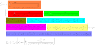
In order to find the derivative of the function, we might need to use software called, Maple. In order to make the equation Maple readable, we must turn Equation A4 into Equation A5. Since Equation A5, is really complex (but Maple readable), I put some color on it to denote relationships between equation A4 and A5. (click image for detail)


Equation A5

After equation A5 have been checked for their compatibility with Equation A1, we will go further to the next step of making calculation network design (required to minimize the number of calculation required).

The other thing that must be done is to find the derivative of acceleration, as the numerical method used in the PPNCGS is Taylor Second Order.

Download NCGS Program and Source Code here

The Wobble of Star caused by Hot Jupiter class planets

Hot Jupiters are planets with mass of several Jupiter orbiting as close as Mercury or Venus to their primary star. Planets with such mass orbiting the primary at close distance, may disrupt the movement of the star, causing it to wobble relative to the star’s proper motion.

To show this effect in detail, we will conduct several experiments with a 1.1775 Solar Mass star called Eltera, by placing one or two Hot Jupiters in the system.

Single planet

The first Hot Jupiter we place in this system is a 4.3359 Jupiter Mass planet, called Sivatra. Sivatra is placed in an orbit, 0.3 AU from Eltera, with initial orbital speed of 59.022 km/s (relative to Eltera). The wobble caused by Sivatra is shown below.

The wobble of Eltera caused by single planet orbiting it is relatively simple, by calculating the period of a wobble, we can calculate the period of Sivatra orbit. Then if we know the mass of the star Eltera, we can work out the radius of Sivatra orbit. By analyzing the strength of the wobble and taking the radius of Sivatra orbit, we can derive the mass of Sivatra.

Two planets

Now, how if we add another Hot Jupiter called, Ertina, with mass of 2.7558 Jupiter Mass into the Eltera System ? How the shape of the wobble will be ?


It turns out that depending on the starting position of Ertina relative to Sivatra, the shape of the wobble will be different, but there is a clear clue in the plot result, hinting that there are two planets in the system. The clue is the fact that in all figure above, all plot results shows retrograde movement, with two different period.

By analyzing the time difference per two knots over different time ( with the same method used to examine the plot result of sin(a*t)+sin(b*t) to derive the value of 2*Pi/a and 2*Pi/b ), we can derive the period of each planets. If the mass of Eltera is known, we can later derive the distance of each planets from Eltera, which is the information needed to calculate the mass of each planets.


Download NCGS Program and Source Code here

The movement of planet with eccentric orbit relative to other planet with eccentric orbit

I had written a blog before about the movement of planets relative to other planets, but later I realized that in that blog, I only explained about planets occupying orbits with low eccentricty. The movement of planets with eccentric orbit relative to other planets with eccentric orbits is as interesting, if not more interesting, than if all planets occupy almost circular orbit.

For this experiment lets have a system consisted of a star, a hot jupiter and 3 earth sized planets. The Star is called Vigan ( yellow ), the Hot Jupiter is called Ephemis ( brown ). The three Earth sized planets are Miula ( magenta ), Sihen ( green ) and Altiva ( red ).

Vigan System

The yellow circle is Vigan, the primary star of Vigan system. The brown path is the orbit of Ephemis, the Hot Jupiter. The magenta math is the orbit of Altiva, and the green path is the orbit of Sihen, and the red path is the orbit of Altiva.

movement of planets in Vigan System relative to Ephemis

movement of planets in Vigan System relative to Altiva

movement of planets in Vigan System relative to Sihen

movement of planets in Vigan System relative to Miula

All plot results above show that the retrograde motion of a planets relative to other planets in the system, is more complex than if all planets occupy almost circular orbit.

The movements of planet relative to other planets are interesting things to experiment with. The plot results always show different and interesting new shapes. Whether we can somehow control the shape of the plot result by some kind of mathematic equation, is something I am interested to study.

Download NCGS Program and Source Code here.

The effect of black hole passing by our solar system ( Experiment 2 )

Most people think that if a black hole is passing by our solar system, the black hole is going to suck everything in the solar system, into it. This is not entirely true, matter only get sucked by a black hole if it pass too close to it. Once matter enter the event horizon, there will be no way back, but the Schwarzchild Radius of a black hole is far less than the size of our solar system.

For a comparison, the size of the Sun is far smaller than the size of the solar system, and a black hole is something that have far higher density than ordinary star like our Sun. From these facts, we can easily know that a black hole ,with the same size as the Sun, will have smaller Schwarzchild Radius than the size of the Sun, so it must be several order of magnitude smaller than the size of our Solar System.

What we have to worry about if a black hole passing by our solar system is not about getting sucked into it, like most people believe. We have to worry about the effect of its gravity, which may disrupt the orbit of some planets in our solar system. For example, a black hole passing by between Mars and Jupiter, may disrupt the "stability" of asteroid belt, causing it to enter the inner region of solar system. This may increase the probability of meteors hitting the inner planets.

Fifth Case - 1000 Solar Mass Black Hole

In this experiment, a 1000 Solar Mass Black Hole is going to pass the solar system plane, 1.26 AU from the sun, 2.26 AU from earth. All planets are lining up in one side of the solar system, while the 1000 Solar Mass Black Hole "hit" solar system in the opposing side. Initially the black hole is 9.6E12 m ( 64,000 AU ) away from the solar system plane, and closing the solar system with speed of 0.1c. ( click image for more detail )

As seen from the experiment result, the Black Hole had pulled the Sun, and disrupt the orbit of outer planets. The only "surviving" planets are Mercury, Venus and Earth, but Venus and Earth now have orbit with greater eccentricity. This may cause Earth to be baked by the Sun in the closest point, or frozen in the farthest point, which will surely disrupt the biosphere. Sun have been pulled away by the black hole, causing the outer planets to be left behind, becoming rogue planets, planets that don't orbit any star.

There is a feature that interest me in bottom left picture, which is about the movement of other planets as viewed from Earth. The movement of planet lefts behind by the Sun relative to Earth, display something called retrograde movement, caused by the fact that Earth is orbiting the Sun. This movement is in fact, was one of the sign that not all celestial bodies orbit earth, like geocentric theorist believed.

Sixth Case - 1000 Solar Mass Black Hole

In this experiment, a 1000 Solar Mass Black Hole is going to pass solar system plane, 3.3333 AU from the Sun, between the orbit of Mars and Jupiter. Initially the black hole is 9.6E12 m ( 64,000 AU ) away from the solar system plane, and closing the solar system with speed of 0.01c. ( click image for more detail )


The experiment result shows, that most planets orbit was disrupted so badly, that the only "surviving" planets is Mercury and Earth. All the outer planets have at one time pass the Sun in close distance ( top-left ). Jupiter was especially so close to the sun, that we can expect it to become a gigantic comet for several days, before escaping to the interstellar space. Both Mercury and Earth now, occupy orbits with greater eccentricity than originally was.

The other interesting features is the movement of Earth relative to Mercury and Mercury relative to earth, after the black hole leave our solar system plane (mid-right and bottom left). The movement of both Earth relative to Mercury and Mercury relative to Earth are chaotics, and exhibit a shape of "&". This had lead me to plan for the next experiment about "the movement of planet with eccentric orbit relative to other planet with eccentric orbit", which I will upload later.

Seventh Case - 1000 Solar Mass Black Hole

This 7th experiment is the same with the 6th experiment, except that now I use 100 Solar Mass Black Hole. ( click image for more detail )

The experiment result shows, that all inner planets had "survived" but have to exhibit more eccentric orbit. The new orbit of Mercury and Earth have some point where they are so close, that there might be two probability that can happen, Mercury may hit Earth sometimes in the future, or Earth may slingshot Mercury away as they come close enough but didn't hit each other. The disruption caused by the black hole had caused all the outer planet to escape the Solar System.

In all experiment, I realize that there is something general there. It is easier for black hole to disrupt the orbit of outer planets, while it is harder to disrupt the orbit of inner planets. Planets close to the sun, have smaller probability of being thrown away from the solar system, even if they have to occupy orbit with higher eccentricity after the black hole had leave the solar system.

Download NCGS Program and Source Code here

Saturday, January 12, 2008

Newtonian Collision less Gravity Simulator

Newtonian Collision less Gravity Simulator

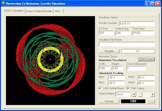
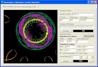
Newtonian Collision less Gravity Simulator (NCGS) is a program made to simulate the interaction between celestial bodies due to a force called gravity. As the name suggests, the simulator is based on Newtonian Gravity, and it is assumed thatcollisions between objects do not occur. The assumption that collisions never happen is based on the fact that the size of celestial bodies are very small compared to the distance between celestial bodies. The other assumption is that celestial bodies are point-sized.

What information does a NCGS need in order to make a simulation? There are several pieces of information required in order to make a simulation with a gravity simulator, they are :
- Gravity Constant
- The mass of celestial objects
- The position vector of celestial objects
- The velocity vector of celestial objects

Why do I see celestial objects colliding in an NCGS, but act as though they never collide? Since the distance between celestial bodies, even inside a planetary system, is astronomical compared to the size of celestial bodies themselves, the size of the icons representing each celestial bodies are thus not drawn to scale. If we are to make a true scale simulation, with one pixel sized icon representing earth, then we would need 12500 pixels to represent the distance between Earth and the Sun ( I think this is greater than the maximum resolution of most monitors, or the maximum resolution that common Graphic Accelerator can handle ). So objects seemingly collide in NCGS, have a high probability of not actually colliding.

The Math behind NCGS

Download NCGS Program and Source Code here

Preview

Inner Solar System (Plus Jupiter) without Trailing

Inner Solar System (Plus Jupiter) with Trailing

The effect of a black hole passing by our solar system

The effect of a black hole passing by our solar system

When we discussing about astronomy, there are lots of interesting questions which reflects our interests about the universe, come out from the creative mind of science fiction fans. One of them is about what happen to our solar system if a black hole enter and pass by our solar system. Of course the answer depends on how big the black hole is, and where on the solar system plane, the black hole passes by.

Here I will show the result of my experiment, not using actual stars, planets and black holes, of course, as you can believe me, I am not strong enough to throw a black hole to a solar system, and I am not rich enough to have more than one solar system at my disposal. NCGS is a good tool to use if we want to do some experiments, inexpensive compared to using real solar system and black hole.

As the NCGS that I use doesn’t take relativistic effect into account, I will use black holes, moving at 3E7 m/s or 0.1 c (so the relativistic effect can be neglected), to bombard a model resembling our solar system.


First Case - 100 Solar Mass Black Hole, Opposing Side

The first case here is the one where a 100 Solar Mass black hole is closing by from a place 2E12 m ( 13.333 AU )above the solar system plane, with speed of 3E7 m/s ( 0.1c ). The black hole will spend about two days inside the 2E12 m sphere with sun at the center, and intersect the solar system plane, 189,590,000 km ( 1.2639 AU ) away from the Sun, and 339,590,000 km away from Earth. (click image for more detail)

The result is that the black hole only gives Sun and any other planets inside the solar system, some acceleration, then leave it alone. The Sun is accelerated, along with other planets, but the planets still orbit the Sun as if nothing had happened. This is because the tidal force of the black hole is not enough to break the formation of the solar system.


Second Case - 1000 Solar Mass Black Hole


So the next we will use a bigger black hole, with 1000 Solar Mass. The black hole is closing by from a place 4.8E12 m ( 32 AU ) above the solar system plane, with speed of 3E7 m/s ( 0.1c ). The black hole will spend about two days inside the 2E12 m sphere with sun at the center, and intersect the solar system plane, 189,590,000 km ( 1.2639 AU ) away from the Sun, and 245,262,110 km away from Earth. (click image for more detail)

Now, the black hole disrupts the orbit of Venus, Mars and Earth and throws them out of our Solar System. Mercury, which lies in the innermost orbit, doesn’t suffer as much as other planet, as the energy of the black hole isn’t enough to throw it out of orbit, but now mercury have an orbit with greater eccentricity.


Third Case - 1000 Solar Mass Black Hole

In the previous experiment, the black hole pass the solar system plane, in the middle of the first and second quadrant, in this experiment will pass the solar system plane, in the middle of the third and fourth quadrant, where all planets are headings to. Now, what will happen if a 1000 Solar Mass black hole intersect the solar system plane, 189,590,000 km ( 1.2639 AU ) away from the Sun, and 234,095,984 km away from Earth. (click image for detail)


Surprisingly, the black hole didn’t do as much damage as if the black hole intersects the solar system plane in the other side. Now Mercury, Venus, Earth and Mars have an orbit with higher eccentricity, but none of them escape the solar system.


Fourth Case - Two 1000 Solar Mass Black Hole

Now, lets consider what happen if something like two 1000 Solar Mass black holes pass our beloved astronomical backyard. See the data inside the image for more information, as the condition involved is a bit complicated. (The two white trail is the path of the black hole)

As we can see, now both Earth and Mars are slingshoted away from the solar system. Some outer planets in other hand are closing to the sun. We can see the orbit of Jupiter, Saturn and Uranus, inside the 1E12 m radius from the sun. If big planets are closing by the Sun, then it is also likely that objects like the asteroid belt will also come to the inner part of the solar system, putting the inner planet ( if they are still inner planet ) into the danger of meteor shower. But the giant planets closing by have some probability to offer some protection from this catastrophe.

Black hole passing a planetary system doesn’t always seems to bring too much trouble if the black hole is in the order of 100 Solar Mass, as the tidal force is not enough to disrupt the planetary system. Black hole in the order of 1000 Solar Mass is of course more dangerous, but they are as rare as stars with equal mass, so it is not really something to worry about.

There are still thousands of interesting scenarios to try out, and I am still work out on a Black Hole Catastrophic Probability Simulator, which will be capable of simulating more than one scenario, I will upload them later.

The Orbit of Planets as seen from other Planets

The plot result of the movement of planets, as seen from other planets is interesting to study. One of the interesting points is the fact that if a planet orbits the sun in circular orbit, the plot of the sun movement relative to that planet will also form a circular "orbit". This is by no means saying that if a planet orbits the sun, then it is equivalent with sun orbit the planet.

The planet is not inside inertial reference frame, since it is accelerated by Sun’s gravity, which is greater than the gravity of any planet. So the planet change reference frame all time, which is why the “movement” of Sun relative to a planet (assuming that the planet is have mass far less than the Sun), is called imaginary movement.

The movement of other planets, as seen from Earth

By putting earth as the centre of the coordinate system used to plot the movement of other planets, we can see an effect usually called retrograde motion. The motion of Mercury for example, resembles a closing and distancing motion, with great knot, caused by the movement of both Mercury and Earth. The “orbit” of Sun, forms a circle with radius equal with the orbit of Earth. The most interesting one for me is the movement of Venus, which have small knot, and the total orbit making a shape resembling a pentagonal flower.


The movement of other planets, as seen from Mercury

By putting Mercury as the centre of the coordinate system used to plot the movement of other planets, we get the picture above. As Mercury is the innermost planet, the knot formed by the movement of other planets relative to Mercury is big. The total plot resembles something like the eye of a lizard.


The movement of other planets, as seen from Venus

The movement of Mars, as seen from Venus is something interesting for me. Instead of forming a circle with lots of knots inside, like the movement of other planets, the movement of Mars relative to Venus forms an 8. This is because the distance of Venus and Mars, when Mars is near the 5’o clock and 11’o clock direction of Venus, is always the same.

The movement of other planets as seen from Mars

The movement of Earth and Venus relative to Mars are the most interesting feature in this plot result for me. As the movement of Mars forms an 8 as seen from Venus, the movement of Venus as seen from Mars is also forming the same shape. This is because the distance of Mars and Venus, when Venus is near the 5’o clock and 11’o clock direction of Mars is always the same. The movement of Earth forms some kind of flower shaped form, with seven sides. This is of course doesn’t have any relationship with the fact that there are flowers in earth. :)

My conclusion about these experiments is that forms, made by the movement plot of an object A relative to another Object B, is always the same with the movement plot of object B, relative to object A.

The movement of other planets as seen from outer planets will be uploaded later.

Friday, January 11, 2008

Multiplexer and Demultiplexer

Multiplexer and Demultiplexer are simple device made from basic logic gates. The devices are basic parts of Read Only Memory (ROM), Random Access Memory (RAM), and Arithmetic Logic Unit(ALU).

Multiplexer is a device used to select one of several input as the output of the device (Out).
The device works by selecting the input choosen by S1,S2,S3.

Demultiplexer is a device used to select one of several output line, to which it must transfer an input (In) value.
The device works by selecting the output choosen by S1,S2,S3.

Basic Logic Gate

Logic gates are the basic parts of binary computers. Basically what logic gates do is mapping one, two or more digital signal into a digital output. There are basically 8 kinds of logic gates, they are AND, OR, NOT, NAND, NOR, XOR, NXOR, and BUF.

AND logic gate gives true (1) output, if and only if, all of its input are true (1).
OR logic gate gives true (1) output, if and only if, at least one of its input are true (1).
NOT logic gate is a single input single output logic gate, which output is the negation of its input.
NAND logic gate gives false (0) output, if and only if, all of its input are true(1).
Basically it can be thought as if a NAND logic gate is a combination of an AND and a NOT logic gate.
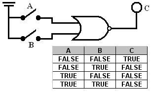
NOR logic gate gives false (0) output, if and only if, at least one of its input are true (1).
Basically it can be thought as if a NOR logic gate is a combination of an OR and a NOT logic gate.

XOR logic gate gives true (1) output, if and only if, the number of its true (1) input are odd.


NXOR logic gate gives true (1) output, if and only if, the number of its true (1) input are even.
BUF logic gate is a single input single output logic gate, which output is the same as its input.
Probably it doesn't make sense that there is such gate, but actually it have its own application in digital electronics as signal amplifier.